¶ System settings
Your Altion Voltage Regulator uses a web-based interface for configuration. Follow the steps below to connect and access the configuration settings.
You must have your regulator correctly wired and installed according to the Altion Installation Instructions before proceeding with configuration.
Latest Firmware Features: These configuration options and features reflect the latest version of the Altion firmware. Older firmware versions may not support all features and may operate differently. To ensure you have access to all capabilities, enable automatic updates or manually update through Revatek Connect.
¶ Connecting to the Altion Regulator
This section describes how to connect to your Altion regulator's web interface for configuration. There are two main connection scenarios:
-
Direct Connection (Initial Setup): Connecting directly to the Altion's built-in Wi-Fi network. This is the typical method for initial setup.
-
External Network Connection: Connecting to the Altion through an existing Wi-Fi or Ethernet network (e.g., your RV or boat network).
¶ Direct connection (initial setup)
Use these steps when setting up your Altion for the first time, or if you haven't yet connected it to an external network.
-
Power On: Ensure your Altion regulator is properly installed and receiving power. You will see the red power light turn on, and for the Altion Max, the screen will turn on and show a prompt for configuration. Older firmware will show a white pixelated background. This indicates Altion is ready for configuration.
-
Locate the Altion's Wi-Fi Network: The Altion creates its own Wi-Fi network. The network name (SSID) will be in the format
Revatek-XXX, where "XXX" represents the last three digits of your Altion's serial number. Use your phone, tablet, or computer to scan for available Wi-Fi networks. -
Connect to the Network: Select the
Revatek-XXXnetwork from the list. This network is open (no password required) for initial setup. -
Access the Web Interface: Open your web browser (e.g., Chrome, Firefox, Safari) and enter the following address into the address bar:
regulator.localand press Enter. If this will not connect, try192.168.0.1. This will take you to the Altion's web interface. You can now configure your Altion.
¶ Connecting via an external network
Important: Do not interrupt the device during factory reset or firmware updates, as this may cause system instability.
Internet Connection: We recommend using a purpose-built hotspot, Ethernet, or Wi-Fi network (e.g., Starlink) for the best experience. These connections include routers that allow you to access the device via
regulator.local.Need to use a phone hotspot? It is possible but requires specific steps. See our Phone Hotspot Update Guide
If you've already configured your Altion to connect to your RV or boat's Wi-Fi network (or a wired Ethernet connection), the Altion will have a different IP address assigned by your router.
-
If you have an Altion Max: The easiest way to find the IP address is to check the OLED screen on the Altion Max. The assigned IP address will be displayed.
-
If you don't have an Altion Max (or can't access the screen):
- From a Web Browser: In your address bar, type
regulator.localand press Enter. If this will not connect, try192.168.0.1. This may work if your computer and the Altion are on the same network and your computer has network discovery enabled (using a protocol called mDNS or Bonjour). If this doesn't work, you'll need to use the router method. - Check Your Router: Most routers have a web-based administration page where you can view a list of connected devices. Look for a device with the hostname
regulator. The IP address will be listed next to it. Consult your router's manual for instructions on accessing this page, as it varies by manufacturer and model.
- From a Web Browser: In your address bar, type
¶ Troubleshooting
- If you cannot connect, ensure the Altion is powered on and within range of your Wi-Fi device or router.
- If you are still having trouble, consult the full Altion User Guide for more detailed troubleshooting steps.
- Network Reset Only (Firmware 20250916+): If your firmware is version 20250916 or newer, a quick double-tap of the button on the right side of the Altion will reset the network settings. This causes it to create its own network (
Revatek-XXX) once again, allowing you to connect to the device at192.168.0.1while preserving your configuration. - Factory Reset: For older firmware, or to completely reset your Altion to factory settings, hold down the button on the right side of the Altion for >15 seconds. For firmware v20250916+, the blue network LED starts blinking. After ~2 minutes, the device restarts and completes the reset process. This will reset network settings and all configuration.
Important: Do not interrupt the device during factory reset or firmware updates, as this may cause system instability.
¶ Configuration settings
You'll see a configuration form with three sections:
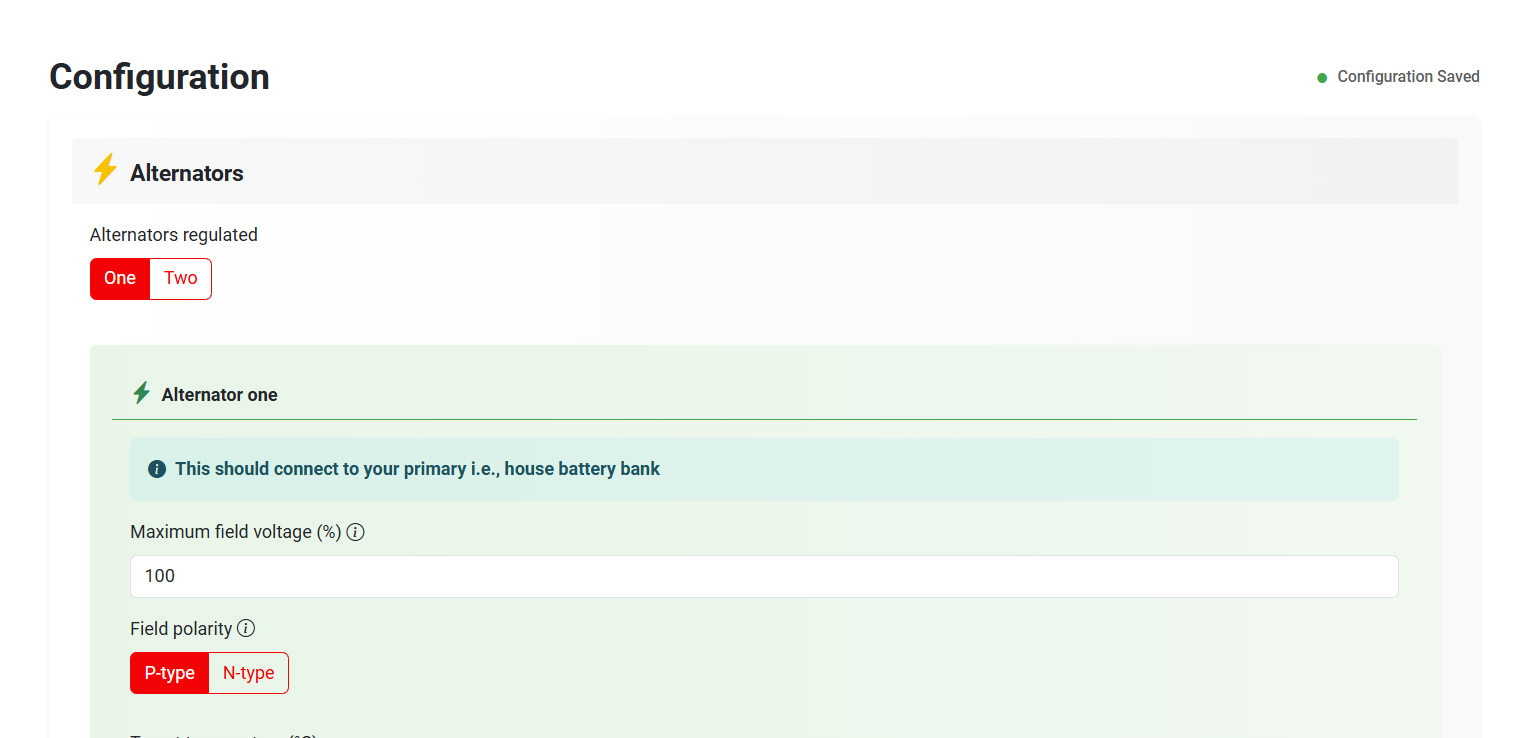
¶ Section 1: Alternators
- Alternators regulated (Altion Max only): Choose whether you have one or two alternators connected to your regulator. For the standard Altion regulator, this option will not appear.
- Battery connected to alternator (Altion Max only): If you have more than one battery bank, the regulator needs to know which one this alternator directly charges. Most setups will only have one battery bank. For the standard Altion regulator, this option will not appear.
- Maximum field voltage: The maximum field voltage the regulator will allow as a percentage of the battery voltage, typically set at 100%. Use this setting to derate your alternator. This setting automatically scales certain alternator control values (Minimum field drive and RPM power reduction) to prevent exceeding the alternator's field power capability.
To derate your alternator, reduce this setting. For example, if you want to limit an alternator that bulk charges at 14v to operate at half field power, set this at 50%. Many 48v alternators operate their field at ~12v, so you may need to reduce this to prevent overvoltage. Consult your alternator's data sheet.
- Field polarity: Most modern alternators are "P-type", but check your alternator's documentation if unsure.
- Target temperature: The ideal operating temperature for your alternator. The regulator will adjust its output to help maintain that temperature.
- Startup delay: Allows a brief delay after engine start before the regulator begins charging, giving the engine time to settle. Leave blank to disable setting.
- Stator sensor installed: Select this if you have a stator sensor attached to your alternator. If you make this selection, you will see additional options for configuring how the regulator uses the stator sensor data to optimize charging and manage engine load (via RPM). In addition, this feature displays RPM on the dashboard and disables the alternator field when the engine is off.
- Engine : Alternator pulley diameter ratio: The ratio of the pulley diameters of the engine to alternator. For example, if engine the pulley is 6 inches in diameter and the alternator pulley is 3 in diameter, the ratio is 2.
- Number of alternator poles: The number of alternator poles. Check your alternator manual or contact the manufacturer.
- Minimum field drive: The minimum field drive as a percentage of full field. This value is automatically scaled by the Maximum field voltage setting. For example, if maximum field voltage is 50% and minimum field drive is 10%, actual minimum field drive is 50% x 10% = 5%.
If
stator sensor installedis enabled, minimum field drive must be sufficiently high for the Altion to detect RPM at idle. Otherwise, the Altion will not charge. Keep the setting as low as possible while keeping reliable RPM readings on the dashboard at idle in order to prevent unintended charging. This is particularly important for lithium battery setups. Every alternator is unique, so tuning is required. 6% is a typical starting point.
- Reduce power draw at specified RPM: These RPM power reduction values are automatically scaled by the Maximum field voltage setting and should not be used if the regulator receives engine load data. For example, if you set max field voltage at 25% of your battery voltage, and you reduce power draw at a given RPM by 50%, the regulator will power the field at 12.5%, which is 25% x 50%.
- Boost mode: Intelligently boosts charging power whenever engine speed is stable and the vessel is stationary or moving slowly (under 1 knot if GPS data is available via NMEA 2000 or RV-C), maximizing alternator output across all RPM ranges. Automatically adjusts back to normal operation when RPM fluctuates or when underway, ensuring optimal balance of propulsion and charging while preventing boost mode engagement during vessel operation.
- Engine load threshold to disable alternator: If engine load is provided via CAN bus, this setting diables the alternator when the engine is operating above the load threshold.
- Alternator current shunt installed: Select this if you have the current shunt normally connected to battery 2 instead connected to alternator 1. If measuring current for two alternators, the battery 1 shunt is connected to alternator 2.
If selected, you will need to specify the shunt's capacity (amps) and voltage rating.
¶ Section 2: Batteries
Battery type matters! These settings are heavily dependent on whether you have a lead-acid, AGM, lithium, or another battery type. Consult your battery manufacturer or a battery professional for recommended values to enter here.
- Prepopulate battery bank specifications: Save time if you know your battery type, brand, model and voltage – simply select these from the dropdown lists.
If your battery type, brand, model and voltage is found, the battery settings below will automatically be filled out with the manufacturer's recommended settings. You should still verify these settings against your battery's documentation.
Disclaimer: These settings are provided based on battery manufacturer recommendations for convenience and we make no representation as to the functionality, safety or compatibility of these batteries.
Do not use non-CAN bus connected lithium batteries in systems above 12V
- Battery voltage sense installed: Select this if you've installed a sensor that lets the regulator directly monitor battery voltage.
This is highly recommended for accurate charging. - Temperature sense installed: Select this if you have a temperature sensor on your battery. The regulator uses this to protect batteries during charging, especially critical for lithium batteries.
If selected: Enter the temperature range the regulator should use to control charging (protects against damage from extreme temperatures). - Temperature compensation slope: Allows for fine-tuning of the charging voltage in response to changes in ambient temperature. This setting automatically increases the charging voltage when the temperature is below 25°C and decreases it when the temperature is above 25°C. This optimizes battery charging and longevity, especially for lead-acid batteries which are sensitive to temperature variations.
This input should be one or greater millivolts per degree Celsius, otherwise leave blank to disable setting. - Current shunt installed: Select this if you have a device that lets the regulator accurately measure current flow in/out of the battery bank. Highly recommended for advanced battery monitoring and health.
If selected, you need to specify the shunt's capacity (amps) and voltage rating, amp hours and maximum charge rate to optimize charging.
Battery Current Targeting: When a current shunt is enabled, the Altion will target the minimum of: (1) Battery bank maximum charging C-rate × Battery bank amp hours (Ah), or (2) target current received over CAN bus. This ensures safe charging within both configured limits and external system requests.
- Charging profile: Your battery goes through different stages to ensure it gets fully charged, stays healthy, and isn't overcharged. This subsection lets you fine-tune how your Altion regulator handles those stages.
¶ Bulk + Absorb
- Charging Voltage: The main target voltage the regulator will try to reach. Higher voltage = faster charging, but you must make sure this is safe for your battery type.
- Minimum Time in Charging Stage: Prevents the regulator from switching to the next stage too quickly, even if the voltage target is reached. This helps if your battery was deeply discharged. Leave blank to disable setting.
- Maximum Time in Charging Stage: A safety feature - after a certain time, the regulator will move to the next stage even if the voltage target hasn't been hit. This prevents endless charging if something isn't right. Leave blank to disable setting.
- Field Power Target Min Until Transitioning to Float: Lets you control switching from Bulk/Absorb to Float based on how much power the alternator is generating. This setting applies only if no shunt is installed. This is an absolute percentage that does NOT scale with the Maximum field voltage setting.
- Current Min as Percent of Battery Capacity: Lets you control when the regulator moves to Float based on how much current is flowing into the battery. This setting applies only if a shunt is installed.
- Use Additional Absorb Stage (Post CV): Less common setting, as most setups won't need this. It adds a second "Absorb" stage to top the battery off without risk of overcharging.
¶ Float
- Charging Voltage: A low voltage meant to maintain your battery charge once it's full. The goal is to compensate for any small usage, without over stressing the battery long-term.
- Minimum/Maximum Time: Lets you set time limits in Float mode for additional safety or customization. Leave blank to disable setting.
- Go to Previous Phase if Voltage Drops: If the battery voltage falls too low in Float (could mean a heavy load), the regulator will go back to actively charging. Leave blank to disable setting.
- Go To Previous Phase if Field Power Target Exceeds: If the alternator is having to maintain significant power just to maintain a voltage, the regulator will go back to actively charging. This setting applies only if no shunt is installed. This is an absolute percentage that does NOT scale with the Maximum field voltage setting. Leave blank to disable setting.
- Go to Previous Phase if Amp Hour Draw Exceeds: If the batteries drain this percentage of their capacity, the regulator will go back to actively charging. This setting applies only if a shunt is installed. Leave blank to disable setting.
¶ Additional settings
- External alternator charge cutoff installed: Check this box if you have an external charge cutoff device wired to your regulator. This section allows you to connect an external device that will automatically stop the regulator from charging the battery bank under specific conditions. This can be used for over-temperature protection: If your batteries have a built-in safety mechanism, you can connect it to trigger a cutoff if temperatures get too high. It can also be used for system-level controls: You might have a more sophisticated battery management system that wants to stop charging under certain circumstances.
If selected, you will need to indicate the charge cutoff polarity:
- Low signal: Recommended. Charging will occur when the input is HIGH (receiving voltage), and charging will DISABLED when the input goes LOW (grounded by the external device).
- High signal: Charging will occur normally when the input is LOW (grounded), and charging will DISABLE when the input goes HIGH (receives voltage from the external device)
Configuring this incorrectly could lead to unexpected behavior or damage. The signal type that will tell your regulator to stop charging. Make sure your external charge cutoff device is compatible with the signal type you select here.
¶ Section 3: Network
¶ CAN bus
Most CAN bus batteries use the RV-C standard, but use proprietary communication messages. The Altion will use any compatible data received over the CAN bus over all enabled protocols to supplement or replace its analog data sensors. For any given measurement, the device will revert to analog sensor input if no data is received within a 5 second interval. Battery and alternator volts must be received from analog sources, as CAN bus data does not refresh rapidly enough for effective operation.
Important Note on Charge Current Limits: If the Altion receives a charge current limit request via CAN bus from another device (like a BMS), the Maximum charge rate (C-rate) you configure in Section 2 (Batteries) will always be respected as the upper limit by the regulator. If the C-rate is set lower than the CAN bus request, the C-rate setting will override the CAN bus request.
To ensure the CAN bus limit is the effective ceiling, set the Maximum charge rate (C-rate) in the regulator's settings to a value higher than any limit you expect the CAN bus device to request.
- Protocols enabled: Enable one or more CAN bus protocols for the Altion. These include RV-C and NMEA 2000. J1939 and Victron Energy will be automatically enabled if detected. For detailed instructions on configuring the Altion for use with Victron Energy systems, including specific CAN bus settings, see Victron Integration.
Enabling multiple protocols can lead to conflicts if devices on different protocols use the same PGNs. Generally, only enable the protocols you need.
- Charger instance: The instance that the Altion should broadcast representing the alternator charge source.
- For NMEA 2000 / Victron VE.Can: Choose an instance number that is NOT used by any battery or charger on your network. Instance numbers start at 0. For example, if your battery uses instance 0, select instance 1 or higher for the charger.
- For RV-C: Choose any instance number starting from 1. RV-C allows batteries and chargers to share the same instance number. For example, battery instance 1 and charger instance 1 can coexist without conflict.
- Engine Instance: The instance that the engine is broadcasting.
- Number of batteries broadcasting in bank: The number of independent batteries in your battery bank that each broadcast their own data with separate CAN bus instances. Most battery banks broadcast as a single instance (enter 1). Only enter a number greater than 1 if you have multiple batteries that each have their own CAN bus connection and broadcast with different instances. The Altion will aggregate multi-battery setups into a single bank.
- Battery instance(s): The instance(s) that the batteries are broadcasting.
- Require CAN bus to operate (Safety Feature): If enabled, the Altion will only begin charging if it receives valid battery data over the CAN bus. This can prevent damage if the battery is disconnected unexpectedly. Note: This setting is only recommended for systems where a reliable CAN bus connection to the battery monitor is guaranteed.
¶ Wi-Fi / Ethernet
- Regulator hosted Wi-Fi: Your regulator can create its own Wi-Fi network for configuration and monitoring.
- External Wi-Fi: Join the regulator to an existing Wi-Fi network for reliable connectivity and system integration. Click "Scan" to view and select available Wi-Fi networks.
- No Wi-Fi / Ethernet only: For wired connections to an existing network with maximum robustness and reliability.
- Network name: SSID for regulator hosted and external Wi-Fi networks.
- Network password: Password for regulator hosted and external Wi-Fi networks. Leave blank for none.
¶ Configuration lock
- Configuration password: Create password to modify configuration. Leave blank for none.
Write down the password. Once the password is set, changing settings requires factory reset.
¶ Software update
- Automatic updates: Enable automatic over-the-air updates through Revatek Connect. Once enabled and connected to a network with internet access via Wi-Fi or Ethernet, the Altion will automatically check for updates within 5 minutes and typically complete updates within 10 minutes over a fast Internet connection. This ensures you have the latest features, performance improvements and security fixes. The current firmware version can be found near the bottom of the Configuration page and on the Device Information page.
Update Process: While the Altion is updating, the blue network LED blinks 3 times every 5 seconds until it reboots. The online dashboard will also display the update status with real-time progress. Allow up to 25 minutes for updates to fully install over slow internet connections.
Avoid interrupting updates. Your regulator must have a reliable internet connection for updates to function. Avoid powering off the regulator or interrupting the update process once it has started. While the Altion does include robust roll-back capability, power losses will delay the update process.
¶ Submitting and Saving Configurations
- Submit button: Once you've entered your settings, click "Submit" to send them to the regulator. After submitting, the Altion network will reset to apply the changes. You may temporarily lose connection to the web interface. If you changed the network settings, you may need to reconnect to the device's network on your phone/tablet/PC.
Update Warning: If the device is connected to an external network and Revatek Connect / Software Updates are enabled, following submission it may start normally, then pause for ~3 minutes as it installs a software update. Do not turn the device off or restart it during this period. Wait for the blue network LED to stop blinking before taking any action.
Troubleshooting: Following configuration submission (and any updates), if the device powers up and the field engages on the dashboard but the alternator does not charge, restart the device by pressing the Altion reset button OR turn the ignition off then on again.
- Check for faults: After submitting the configuration, verify there are no faults by checking one of the following:
- The blue light on the Altion is not blinking.
- The top of the dashboard does not show a fault indication.
- Import configuration: Click "Import Configuration" and select a previously saved configuration file to easily load settings.
- Export configuration: Click "Export Configuration" to save your current configuration as a file for backup or to use on multiple regulators.
If you have any problems with the configuration process and must start over, not to worry! You can easily factory reset the device by holding down the button on the right side of the device for 15+ seconds until the blue network LED starts blinking. The LED will continue to blink until the device restarts and completes the reset process. After doing so, wait up to 3 minutes as the device resets its firmware. Do not power off during this period. During this process the Altion will recreate its own Wi-Fi network and reset all settings. Once you see this Altion Wi-Fi network and can load the configuration page, the factory reset process is complete. On the Altion Max, you will see the screen prompt for configuration. Following reset, reconfigure the Altion in order for it to operate.
¶ Network connectivity
This document lists the Parameter Group Numbers (PGNs) supported by our products for RV-C, NMEA 2000 and J1939 communication. PGNs are standardized identifiers used in these networks to define the content and structure of data messages. Understanding the supported PGNs helps determine the compatibility and functionality of our products within CAN bus ecosystems.
¶ Supported PGNs
¶ RV-C
| PGN | Description | Type |
|---|---|---|
| 130762 | Diagnostic Message for RV | Housekeeping |
| 130454 | Generic Revision Request | Housekeeping |
| 130455 | Generic Revision Status | Housekeeping |
| 60671 | Initial Packet | Housekeeping |
| 59392 | ISO Acknowledgement | Housekeeping |
| 60928 | ISO Address Claim | Housekeeping |
| 59904 | ISO Request for PGN | Housekeeping |
| 130774 | Manufacturer-Specific Address Claim Request | Housekeeping |
| 65259 | Product Identification | Housekeeping |
| 60415 | Data Packet | Housekeeping |
| 131013 | Charger Command | Data Sending / Receiving |
| 131012 | Charger Configuration Command | Data Sending / Receiving |
| 131014 | Charger Configuration Status | Data Sending / Receiving |
| 130966 | Charger Configuration Status 2 | Data Sending / Receiving |
| 130764 | Charger Configuration Status 3 | Data Sending / Receiving |
| 130751 | Charger Configuration Status 4 | Data Sending / Receiving |
| 131015 | Charger Status | Data Sending / Receiving |
| 130723 | Charger Status 2 | Data Sending / Receiving |
| 130506 | Charger Status 3 | Data Sending / Receiving |
| 131060 | Chassis Mobility Status | Data Sending / Receiving |
| 131071 | Date Time Status | Data Sending / Receiving |
| 131005 | DC Load Status | Data Sending / Receiving |
| 130512 | DC Source Connection Status | Data Sending / Receiving |
| 131069 | DC Source Status 1 | Data Sending / Receiving |
| 131068 | DC Source Status 2 | Data Sending / Receiving |
| 131067 | DC Source Status 3 | Data Sending / Receiving |
| 130761 | DC Source Status 4 | Data Sending / Receiving |
| 130760 | DC Source Status 5 | Data Sending / Receiving |
| 130759 | DC Source Status 6 | Data Sending / Receiving |
| 130725 | DC Source Status 11 | Data Sending / Receiving |
| 130719 | Generic Alarm Status | Data Sending / Receiving |
| 61184 | Proprietary | Data Sending / Receiving |
¶ NMEA 2000
| PGN | Description | Type |
|---|---|---|
| 59392 | ISO Acknowledgement | Housekeeping |
| 59904 | ISO Request for PGN | Housekeeping |
| 60928 | ISO Address Claim | Housekeeping |
| 126208 | Request Group Function | Housekeeping |
| 126996 | Product Information | Housekeeping |
| 126998 | Product Information | Housekeeping |
| 61184 | Proprietary | Data Sending / Receiving |
| 127488 | Engine Parameters, Rapid Update | Data Sending / Receiving |
| 127489 | Engine Parameters, Dynamic | Data Sending / Receiving |
| 127491 | Electric Energy Storage Status | Data Sending / Receiving |
| 127495 | Electric Energy Storage Information | Data Sending / Receiving |
| 127506 | DC Detailed Status | Data Sending / Receiving |
| 127507 | Charger Status | Data Sending / Receiving |
| 127508 | Battery Status | Data Sending / Receiving |
| 127510 | Charger Configuration Status | Data Sending / Receiving |
| 127513 | Battery Configuration Status | Data Sending / Receiving |
| 127750 | Converter Status | Data Sending / Receiving |
¶ J1939
| PGN | Description | Type |
|---|---|---|
| 65242 | Software Version | Housekeeping |
| 65237 | Alternator Speed | Data Sending / Receiving |
| 61444 | Electronic Engine Controller 1 | Data Sending / Receiving |
| 61443 | Electronic Engine Controller 2 | Data Sending / Receiving |