Altion installation and user guide
User manual for the Revatek Altion alternator regulator
- Introduction
- Unleash the potential of your electrical system
- Importance of the alternator regulator
- Altion key features
- Importance of proper installation
- Safety guidelines
- Installation
- Compatibility check
- Preparation
- Locating and mounting the Altion voltage regulator
- Wiring harness installation
- Configuration
- Monitoring
- Troubleshooting
- Service & warranty
Introduction
Unleash the potential of your electrical system
Experience a revolution in power management with the Altion alternator regulator. Altion surpasses traditional regulators, delivering unparalleled performance, comprehensive configurability, and unmatched connectivity – all designed to optimize the electrical potential of your boat or RV.
This user manual will be your comprehensive guide to unlocking the full potential of the Altion alternator regulator. We'll walk you through every step, from the streamlined installation process to harnessing the advanced features that make Altion a true game-changer in the world of power management.
Importance of the alternator regulator
The essential role of the alternator regulator in your boat or RV's electrical system
Imagine this: you're cruising along in your boat or enjoying a relaxing evening in your RV when the lights dim and the electronics start to sputter. This scenario can quickly turn your leisure time into a frustrating experience. The culprit behind this could be a malfunctioning alternator regulator, a small but critical component in your vehicle's electrical system.
Understanding the alternator
Your boat or RV's engine powers an alternator, which essentially acts like a miniature generator. It converts mechanical energy from the engine's rotation into electrical energy. This electrical current is then used to power your vehicle's various electrical systems and charge the batteries.
Why you need a regulator
However, the alternator on its own can't regulate the voltage output it produces. Without control, the voltage could fluctuate wildly, potentially leading to disastrous consequences:
-
Overcharging: Excessive voltage can damage your batteries, shorten their lifespan, and even lead to overheating or explosions.
-
Undercharging: Insufficient voltage leaves your batteries depleted, unable to power your essential appliances and electronics.
The regulator's function
This is where the alternator regulator steps in. It acts as the maestro of your electrical system, meticulously controlling the alternator's voltage output. There are two main types of alternator regulators:
-
Internal regulators: These are built directly into the alternator itself. They offer a simple and compact solution, but have significant limitations in precision of control and speed of charging. They typically charge more slowly and do not adjust to the charging needs of different battery chemistries, leading to shorter battery life.
- External regulators: These are separate components mounted away from the alternator. They offer greater control over voltage output and can be upgraded for features like intelligent charging algorithms. These require alternators that are wired for external regulation, many of which come factory-ready, while others can be modified by a qualified technician.
Regardless of the type, the regulator's key functions remain the same:
-
Voltage regulation: The regulator monitors the battery voltage and continuously adjusts the alternator's output to maintain a safe and optimal voltage level. This ensures your batteries are properly charged without being overcharged.
-
System protection: The regulator safeguards your entire electrical system. It can prevent voltage spikes that could damage sensitive electronics and protect the alternator from overheating due to excessive workloads.
-
Intelligent charging (in some models): Advanced regulators, like the Altion, utilize intelligent algorithms to optimize charging based on battery type (lead-acid or lithium-ion) and adjust based on factors like voltage, alternator temperature, current and charge stage. This speeds charging and optimizes battery health and performance.
The alternator regulator plays a vital role in maintaining a healthy and efficient electrical system in your boat or RV. It ensures your batteries are properly charged, protects your electrical components, and allows you to enjoy a reliable and worry-free experience on the water or on the road.
Altion key features
Unprecedented charging efficiency
-
20-35% faster charging than internal and traditional external regulators: Altion's advanced algorithms ensure optimal charging for lead-acid and Lithium-ion batteries, charging them faster and extending their lifespan.
-
Works with any externally regulated alternator: Altion seamlessly integrates with virtually any alternator size or voltage system, handling up to 16 amp fields in systems from 12-48 volts.
-
Intelligent control: Altion utilizes cutting-edge PID control algorithms to maximize charging speed and meticulously fine-tune alternator output, efficiency, and reliability. It dynamically adjusts power based on a multitude of factors, including alternator and battery temperatures, voltage, and amperage.
-
Advanced protection: Altion safeguards your alternator from overheating, even under the heavy loads associated with large batteries and lithium charging.
-
Flexible alternator compatibility: Altion works effortlessly with both P-type or N-type alternators with its supplied wiring harness.
-
Efficient power management: Altion charges only when excess engine power is available, intelligently monitoring engine RPM to prevent unnecessary strain in idle and high output situations.
-
Dual alternator control (Altion Max): For two engine setups, Altion Max coordinates regulation of two alternators in a single device.
Unparalleled battery management
-
Universal battery support: Altion adapts to any battery chemistry, including lead-acid (flooded, AGM) and lithium (LiFePo4), meticulously optimizing charging parameters for each type.
-
Precise measurement: Altion supports current shunts ranging from 25-160 mv and accommodates all amperages, delivering accurate battery current measurement for any battery bank size.
-
Optimized charging: Altion's advanced PID algorithms ensure optimal battery voltage and current, quickly reaching and maintaining a full state of charge while preventing the alternator from overheating.
-
Configurable charge cutoff: Establish a charging cutoff based on user-defined signals, such as relays, voltage spikes, or battery temperature.
-
Dual battery bank control (Altion Max): Altion Max tackles even the most demanding setups, enabling independent charging of two battery banks with potentially different voltages and chemistries.
Effortless setup and configuration
-
Seamless installation: Altion prioritizes ease of use. Utilize our pre-made harnesses for a rapid installation, or leverage the configurable connectors for a customized setup.
-
Simplified wiring: Altion installations require only 5-7 wires in most configurations, with up to 26 connections for elaborate multi-alternator/multi-battery systems.
-
Compact design: The Altion's small footprint (5.1 x 3.1 x 1.2 inches) ensures it fits discreetly into tight spaces.
-
Intuitive configuration: Get up and running in minutes. Select from pre-programmed settings for a wide range of batteries, or customize your parameters for a truly personalized experience.
-
Wireless connectivity: Connect wirelessly using any smartphone, tablet, or PC (Windows or Mac) – no app or cables required.
-
Reliable connectivity options: Altion prioritizes Wi-Fi or ethernet connectivity for superior reliability, extended range, and ease of use compared to traditional Bluetooth options.
Wireless firmware updates
Enjoy the convenience of wireless firmware updates, ensuring your Altion remains at the forefront of technology for years to come.
Importance of proper installation
The Altion alternator regulator plays a vital role in your boat or RV's electrical system, but to reap its full benefits, a proper installation is crucial. Here's why:
-
Safety first: Electrical systems can be complex, and improper installation can lead to electrical shorts, fires, or damage to your vehicle's components. For your safety and the well-being of your boat or RV, consider these options:
-
Do-It-Yourself (DIY): If you're comfortable working with electrical systems and possess the necessary skills, the Altion is designed for a user-friendly installation. Clear instructions and pre-made harnesses are included to simplify the process.
-
Professional installation: For those less confident with electrical work, or for complex setups, enlisting a qualified marine or automotive electrician is highly recommended. They possess the expertise to ensure a safe and efficient installation tailored to your specific needs. In the marine environment, particularly for boats with ABYC (American Boat & Yacht Council) certified electrical systems, seeking a technician with ABYC certification or its equivalent in your country is highly recommended. These technicians have the specialized knowledge to integrate the Altion seamlessly while maintaining compliance with critical safety standards.
-
Optimal performance: While a basic installation will get the Altion functioning, proper configuration unlocks its full potential. An experienced technician can ensure the regulator is programmed correctly for your battery type (lead-acid or lithium-ion) and optimizes charging parameters for maximum performance and battery health. For RVs with CAN-bus (Controller Area Network) based systems, also known as RV-C, a qualified technician can ensure the Altion integrates smoothly and communicates effectively with other RV-C devices, maximizing its capabilities.
Making the right choice
The decision to install the Altion yourself or seek professional help depends on your comfort level and the complexity of your electrical system. The Altion's user-friendly design empowers DIY enthusiasts, while professional installation ensures optimal performance and peace of mind.
Additional resources
For those tackling the installation yourselves, the Altion user manual provides comprehensive instructions and wiring diagrams. You can also access helpful video tutorials and online support resources.
Safety guidelines
Working with electrical systems requires caution and proper procedures to ensure your safety. Here are some essential safety guidelines to follow before beginning the installation of your Altion alternator regulator:
-
Power down completely: Always disconnect your batteries and all charging sources before starting any electrical work. This eliminates the risk of shock or sparks that could cause injury or fire. Use the appropriate battery disconnect switch or remove the negative battery terminal.
-
Double-check, double safe: Once the batteries are disconnected, verify with a voltmeter that there is no residual voltage present before proceeding.
-
Clear work area: Ensure your workspace is free of clutter and flammable materials. This minimizes the risk of accidental spills or sparking that could ignite nearby objects.
-
Knowledge is power: Before starting the installation, thoroughly read the Altion user manual. Familiarize yourself with the components, wiring diagram, and recommended installation procedures. If you have any questions or uncertainties, don't hesitate to consult a qualified electrician.
-
Safety gear: Consider wearing appropriate safety gear such as insulated gloves and safety glasses to protect yourself from potential electrical hazards.
-
Professional help when needed: If you're uncomfortable working with electrical systems or the installation seems complex, especially for boats with ABYC certified systems or RVs with CAN-bus networks, enlisting a qualified marine or automotive electrician is the safest option. Their expertise ensures a safe and proper installation tailored to your specific needs.
By following these safety guidelines, you can minimize risks and ensure a smooth and safe installation process for your Altion alternator regulator.
Installation
Compatibility check
The Altion is designed for use with externally regulated alternators with a nominal voltage range of 12-48 volts, with a full operating range of 8-60 volts.
Verification Steps
To ensure compatibility and safe operation, check the following:
- Nominal voltage: Verify if your alternator's nominal voltage falls within the range of 12-48 volts.
- External voltage regulator compatibility: Ensure your alternator(s) are designed for external regulation or have a suitable conversion kit installed.
- ECU control: This voltage regulator is designed for use with alternators that independent of the engine's ECU (Electronic Control Unit). Most marine main alternators fit this description. In RVs, however, main alternators are often ECU-controlled; the Altion regulator is used with secondary alternators in such setups.
- Alternator avalanche diodes: Avalanche diodes are highly recommended for all setups to protect the regulator from voltage spikes occurring from unplanned battery disconnect events. Note that avalanche diodes are rare among 48v alternators. Consult your alternator manufacturer to confirm their presence.
For 48v setups without avalanche diodes, we highly recommend a CAN bus connected setup through RV-C or NMEA 2000 for optimal charge control and safety.
- Alternator Protection Modules: For additional safeguarding against load dump events, consider using alternator protection modules. These supplement, but do not replace, avalanche diodes.
- Ground Connection (Altion Max with multiple alternators): It's critical that all alternators connected to the Altion share a common ground. This prevents ground loops and potential damage to the regulator.
If you are unsure about any aspect of your alternator's compatibility, consult a qualified mechanic or the alternator manufacturer.
Preparation
Before starting the installation, ensure you have the following:
Required equipment
-
Multimeter: This versatile tool is essential for testing the electrical system before and after installation. You'll need it to measure voltage.
-
Wire strippers/cutters: This tool allows you to safely remove insulation from wires for proper connection.
-
Wire crimpers: Secure connections are crucial. Use crimpers to ensure a reliable connection for any additional wiring needed during installation.
-
Fuse holders and assorted ring terminals/butt connectors: These electrical components are required to connect the voltage regulator.
-
Zip ties and/or cable clips: These fasteners will help you secure the wiring harness at regular intervals along its length, preventing strain on the wires and connections and promoting a clean, organized installation.
Highly recommended equipment
-
Battery shunt: A battery shunt is highly recommended for a more precise charging system. It monitors the current flowing to and from battery bank, allowing the Altion voltage regulator to adjust the charging voltage based on the battery's state of charge and current needs. This can significantly improve battery life and overall system performance. By monitoring current flow, the shunt also provides valuable information about the battery's state of charge, helping you understand how much power you have available.
Optional equipment
Ferrules and ferrule crimper: If you plan to add or change wires going into the regulator, ferrules are critical for a secure connection into the device connectors. Ferrule barrels should be 8-10 mm in length. Most installations do not require this.
Locating and mounting the Altion voltage regulator
Ensuring the optimal longevity of your Altion voltage regulator starts with choosing the right mounting location. Here are some key factors to consider:
- Dry and shaded location: The Altion voltage regulator is not designed for direct exposure to moisture. Choose a dry, well-ventilated location protected from rain, other automotive fluids, water spray, and prolonged sun exposure.
- Proximity to other electrical equipment: The ideal location for the Altion voltage regulator is near other electrical equipment in your system, typically close to the battery bank and/or inverter/chargers. This provides easy access for wiring connections and future maintenance or adjustments. We recommend keeping it near, but not inside, the engine compartment if ambient temperatures frequently reach or exceed 50°C (122°F).
- Wire management: Consider the length and flexibility of your wiring harness when choosing a location. Allow enough slack for easy connection to the battery and other electrical components without excessive strain.
Important Safety and Compatibility Notes
- Battery Disconnect with Aux/Field Disconnect: If using a battery disconnect switch with an auxiliary/field disconnect, route the ignition or Alt + wire through it for safety purposes. Do not route the field wire through this switch.
Battery Switch: To avoid damage to the alternator and electrical system, always ensure the main battery switch is in the ON position before operating the motor and regulator.
Mounting recommendations
- Vibration Dampening and Heat Dissipation: For optimal performance and longevity, use the included rubber washers between the Altion and the mounting surface when mounting your regulator. These washers help dampen vibration and promote heat dissipation.
- Mounting surface: The Altion voltage regulator is designed for mounting on a flat, stable surface. Ensure the chosen location can support the weight of the regulator and provide a secure foundation.
- Orientation: Consider mounting the Altion voltage regulator in a way that optimizes airflow and heat dissipation. If you choose to mount the regulator vertically, we recommend orienting it so the wiring harness exits the left side of the device to minimize the chances of water ingress.
- LED visibility: All Altion voltage regulators feature LED lights to indicate operational status. The Altion Max additionally features an LED display for detailed information. Consider a location where these visual indicators can be easily viewed for monitoring purposes.
Before drilling any permanent mounting holes, use temporary fasteners or double-sided tape to hold the regulator in the desired location. This allows you to double-check accessibility, wiring reach, and overall functionality before final installation.
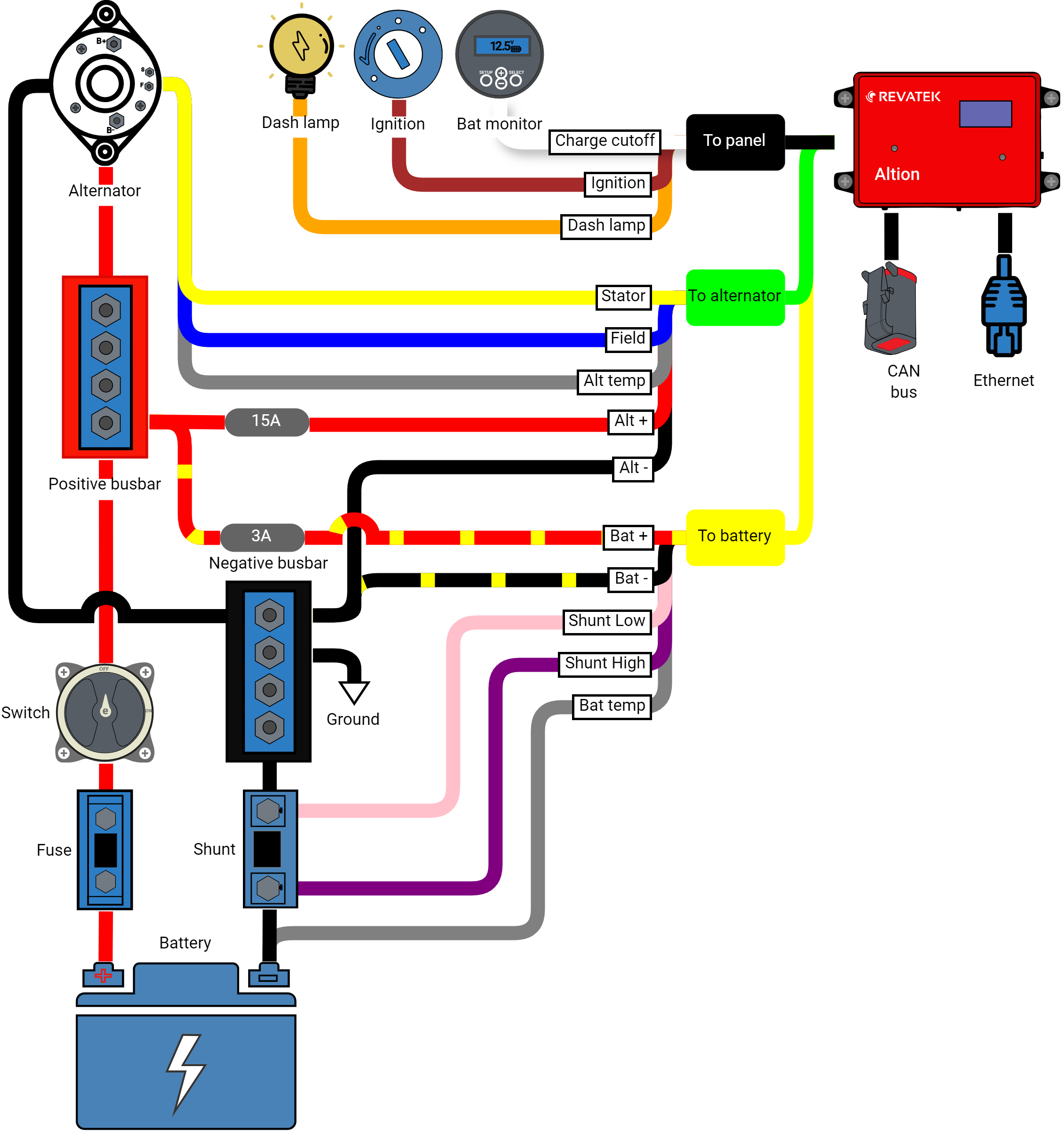
Wiring harness installation
This section will walk you through installing the wiring harness for your Altion voltage regulator. We've included a comprehensive wiring diagram, a detailed wire descriptions table, and helpful tips for a smooth and successful installation.
Understanding your wiring harness
Altion voltage regulators come with wiring harnesses designed for compatibility with your specific model. There are two main harness configurations:
- Single alternator harness (standard): Suitable for systems with a single alternator. It features three sections, each with color-coded wires for easy identification.
- Dual alternator harness (Altion max only): Exclusive to the Altion Max model, this extended harness is designed for systems with dual alternators. It includes two additional sections sleeved in blue and white to accommodate the second alternator and an additional battery. The wire colors within these sections match the standard harness designations, but they connect to the additional alternator and battery bank respectively.
Refer to the wiring diagram below for a visual representation of the single alternator harness (standard). The Altion Max uses the same wire colors and connection instructions. See the following table for a detailed breakdown of wire names, colors, and functions, which applies to both the standard and Altion Max configurations.
Wiring diagram
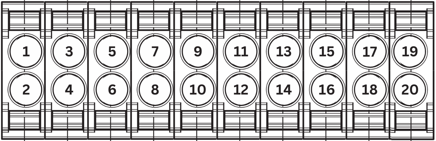
Connector pin numbering
Use these pin numbers and the wiring table below if you need to replace wires. The stock harness uses 18 AWG wire for connections except for Alt +, Alt -, and Field, which use 14 AWG. For extended runs use thicker wire. In most installations, stock wiring is sufficient.
Connector A
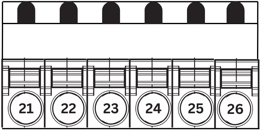
Connector B
Wiring table
Panel wiring harness (black sheathing)
Connector Pin numbers are listed with alternator 1 and battery 1 first, followed by alternator 2 and battery 2, if applicable.
| Wire Name | Color | Description | Connector Pin |
| Ignition | Brown | Provides switched power to the Altion regulator. Connect to ignition switch, oil pressure switch, or a similar circuit active only when the engine runs. For always-on battery monitoring, connect to a positive bus bar (required, 8-60V). | 1, 2 |
| Dash lamp | Orange | Provides a ground path to activate a warning light or audible alarm in the event of a fault condition (optional, 8-60V, 2A max) | 19 |
| Charge cutoff | White | Configurable function to stop charging when the signal line crosses 2V (trigger level adjustable, optional, 0-60V). | 7, 13 |
Alternator wiring harness (green sheathing, blue for Alternator 2 in Altion Max)
| Wire Name | Color | Description | Connector Pin |
|---|---|---|---|
| Alternator Temp | Gray | Connects to alternator temperature sensor. Improves efficiency and protects alternator by regulating field output based on temperature. Mount on rear case or ground terminal. | 8, 5 |
| Alt - | Black | Provides ground to the regulator. Connect to negative bus bar or alternator's negative ground terminal. Ensure clean connection to bare metal. | 23, 26 |
| Alt + | Red | Supplies power for the alternator field. Connect to the positive bus bar or alternator's positive output post. Fuse at 15 amps. (8-60V) | 21, 24 |
|
Field |
Blue | Carries field current between the regulator and alternator. Polarity varies based on alternator type. Fuse if recommended by alternator manufacturer (common for N-type, 16A max). | 22, 25 |
| Stator | Yellow | Provides signal for alternator and engine RPM. Connect to alternator's stator (AC) output or splice into the tachometer output. | 4, 3 |
Battery wiring harness (yellow sheathing, white for Alternator 2 in Altion Max)
| Wire Name | Color | Description | Connector Pin |
|---|---|---|---|
| Bat temp | Gray | Connects to battery temperature sensor. Adjusts charging voltage based on battery temperature, critical for lithium batteries in cold climates. | 10, 16 |
| Bat - | Orange | Improves charging accuracy by monitoring voltage at the battery's negative bus bar or terminal. Connect to the same negative terminal post as the ground cable in multi-battery setups. | 11, 17 |
| Bat + | Black w/ Yellow Stripe | Improves charging accuracy by monitoring voltage at the battery's positive bus bar or terminal. Fuse at 3 amps. Connect to the same negative terminal post as the ground cable in multi-battery setups (8-60V). | 14, 20 |
| Shunt high | Red w/ Yellow Stripe | Connects to the high side of a battery shunt, toward the battery. Measures current flow for charging optimization and battery health. Refer to the diagram. Minimize extension length, use twisted wire if needed. Can be added to existing wiring, so multiple devices can read from a single shunt. |
12, 18 |
| Shunt low | Pink | Connects to the low side of a battery shunt, toward the negative bus bar. Refer to the diagram. Minimize extension length, use twisted wire if needed. | 9, 15 |
Installation instructions
Before installing or working on the Altion regulator, disconnect all power sources and remove the negative battery terminal to prevent electrical shock and equipment damage.
Step 1: Connect wires to the alternator
- Locate the corresponding wires on your alternator following the manufacturer's instructions.
- Strip a small section of insulation (typically 1/4 inch) from the ends of the designated alternator wires (refer to the wiring table and diagram).
- Use compatible crimp terminals (refer to your alternator's manual for terminal type) and secure them to the stripped wire ends using your crimping tool.
- Carefully connect the matching colored wires from the alternator section of the wiring harness to the corresponding terminals on your alternator. For the Altion Max, refer to the wiring table and diagram for connections to the second alternator (blue sleeved section).
Step 2: Connect wires to the battery bank
- Locate the positive and negative battery terminals on your battery bank (and the additional battery bank for Altion Max).
- Strip a small section of insulation from the ends of the designated battery wires (refer to the wiring table and diagram).
- Use compatible crimp terminals and secure them to the stripped wire ends.
- Connect the battery wires to your battery bank(s) according to the wiring table and diagram, paying close attention to connections for the additional battery in the Altion Max (white sleeved section).
Step 3: Connect wires to the panel
- Locate the ignition switch, warning lamp connection point, and any designated points for custom functions on your system's control panel.
- Strip a small section of insulation from the ends of the designated panel wires (refer to the wiring table and diagram).
- Use compatible crimp terminals and secure them to the stripped wire ends.
- Connect the panel wires to your system's control panel according to the wiring table.
Step 4 (optional): Connect to CAN Bus
- Connector: The Altion uses a DTM connector for its CAN bus connection, allowing direct compatibility with RV-C networks. A DTM to NMEA 2000 (M12 connector) adapter is included for connecting to NMEA 2000 networks.
- Termination: Proper termination of the CAN bus is critical for reliable communication. If the Altion regulator is the last device on the CAN bus backbone, set the CAN bus terminator switch to the ON position (switched to the right). This adds a 120-ohm resistor between the CAN High and CAN Low lines. The Altion is installed on a drop line (not the last device on the backbone), in which case the switch should remain off (to the left).
Terminating the CAN bus at more than two points can degrade its performance. You can use a multimeter to test for proper termination by measuring the resistance between CAN High and CAN Low. It should read approximately 60 ohms if the network is properly terminated at both ends.
Step 5: Secure and organize the wiring harness
-
Connect the two alternator harness connectors and align them with the corresponding slots on the left side of the regulator. The connectors are keyed, which means they are designed to fit only in a specific way. Carefully insert the connectors into the slots, making sure that they are fully seated.
-
Double-check all connections: Before applying any power, take a final moment to visually inspect all wire connections for secure crimps and proper placement on the designated terminals.
-
Secure the Wiring Harness: Use zip ties or other suitable fasteners to secure the wiring harness at regular intervals along its length.
-
Route the Wiring Harness: Carefully route the excess wiring harness to avoid any pinch points, hot engine components, or areas with high abrasion potential.
-
Maintain Slack: Allow for some slack in the wiring, particularly near the alternator, battery bank, and control panel connections.
If you need to extend the CAN bus, voltage or temperature sensor cables, use twisted pair wires. For electrically noisy environments, consider using shielded instrument cable for added protection.
With these detailed steps, the comprehensive wiring table, the included wiring diagram, and the added CAN bus instructions, you can ensure a successful and trouble-free installation of your Altion voltage regulator wiring harness.
Configuration
System settings
Your Altion Voltage Regulator uses a web-based interface for configuration. Follow the steps below to connect and access the configuration settings.
You must have your regulator correctly wired and installed according to the Altion Installation Instructions before proceeding with configuration.
Connecting to the Regulator
-
Power on: Make sure your Altion regulator is correctly installed and receiving power.
-
Locate the Wi-Fi network: Out of the box, your regulator will create an open Wi-Fi network. The name will look like "Revatek-xxx" (where "xxx" is a random number). Use your Wi-Fi device (phone, tablet, or PC) and look for this network in your available Wi-Fi connections.
-
Connect to the network: Connect to the "Revatek-xxx" network. Since it's an open network, you won't need a password.
-
Access the web Interface: Open your web browser and type 192.168.0.1 into the address bar and press enter. This will take you to the regulator. Click on the configuration navigation link.
The url address 192.168.0.1 only applies to Altion-hosted networks. If you connect the Altion to an external Wi-Fi or Ethernet network, the Altion will be assigned another network address. Find this address from your router, or if using a PC type the network name in the address bar that you provided in settings to connect to the Altion. The default network name is 'regulator'.
Configuration settings
You'll see a configuration form with three sections:
1. Alternators
-
Alternators regulated (Altion Max only): Choose whether you have one or two alternators connected to your regulator. For the standard Altion regulator, this option will not appear.
-
Battery connected to alternator (Altion Max only): If you have more than one battery bank, the regulator needs to know which one this alternator directly charges. Most setups will only have one battery bank. For the standard Altion regulator, this option will not appear.
-
Max field voltage: The maximum field voltage the regulator will allow, typically set at the bulk charging voltage. This protects your alternator. Use this setting to derate your alternator.
To derate your alternator, reduce this setting. For example, if you want to limit an alternator that bulk charges at 14v to operate at 50% field power, set this at half the bulk charge voltage, i.e., 7v. Many 48v alternators operate their field at ~12v. Consult your alternator's data sheet.
-
Field polarity: Most modern alternators are "P-type", but check your alternator's documentation if unsure.
-
Target temperature: The ideal operating temperature for your alternator. The regulator will adjust its output to help maintain that temperature.
-
Startup delay: Allows a brief delay after engine start before the regulator begins charging, giving the engine time to settle. Leave blank to disable setting.
-
Stator sensor installed: Select this if you have a stator sensor attached to your alternator. If you make this selection, you will see additional options for configuring how the regulator uses the stator sensor data to optimize charging and manage engine load (RPM).
- Engine : Alternator pulley diameter ratio: The ratio of the pulley diameters of the engine to alternator. For example, if engine the pulley is 6 inches in diameter and the alternator pulley is 3 in diameter, the ratio is 2.
- Number of poles: The number of alternator poles. Check your alternator manual or contact the manufacturer.
- Reduce power draw at specified RPM: This allows you to derate the alternator at various RPM levels. This is most commonly used at idle and high RPM. This setting will be be combined with any derating applied by the Max field voltage setting. For example, if you set max field voltage at 25% of your battery voltage, and you reduce power draw at a given RPM by 50%, the regulator will power the field at 12.5%, which is 25% x 50%.
- Boost mode: Intelligently boosts charging power whenever engine speed is stable, maximizing alternator output across all RPM ranges. Automatically adjusts back to normal operation when RPM fluctuates, ensuring optimal balance of propulsion and charging.
2. Batteries
Battery type matters! These settings are heavily dependent on whether you have a lead-acid, AGM, lithium, or other battery type. Consult your battery manufacturer or a battery professional for recommended values to enter here.
-
Prepopulate battery bank specifications: Save time if you know your battery type, model and voltage – simply select these from the dropdown lists.
-
Battery voltage sense installed: Select this if you've installed a sensor that lets the regulator directly monitor battery voltage.
This is highly recommended for accurate charging. -
Temperature sense installed: Select this if you have a temperature sensor on your battery. The regulator uses this to protect batteries during charging, especially critical for lithium batteries.
If selected: Enter the temperature range the regulator should use to control charging (protects against damage from extreme temperatures). - Temperature compensation slope: Allows for fine-tuning of the charging voltage in response to changes in ambient temperature. This setting automatically increases the charging voltage when the temperature is below 25°C and decreases it when the temperature is above 25°C. This optimizes battery charging and longevity, especially for lead-acid batteries which are sensitive to temperature variations. This input should be one or greater millivolts per degree Celsius, otherwise leave blank to disable setting.
-
Current shunt installed: Select this if you have a device that lets the regulator accurately measure current flow in/out of the battery bank. Highly recommended for advanced battery monitoring and health.
If selected, you will need to specify the shunt's capacity (amps) and voltage rating, along with other battery details to optimize charging. -
Charging profile: Your battery goes through different stages to ensure it gets fully charged, stays healthy, and isn't overcharged. This subsection lets you fine-tune how your Altion regulator handles those stages.
-
Bulk + Absorb
-
-
Charging Voltage: The main target voltage the regulator will try to reach. Higher voltage = faster charging, but you must make sure this is safe for your battery type.
-
Minimum Time in Charging Stage: Prevents the regulator from switching to the next stage too quickly, even if the voltage target is reached. This helps if your battery was deeply discharged. Leave blank to disable setting.
-
Maximum Time in Charging Stage: A safety feature - after a certain time, the regulator will move to the next stage even if the voltage target hasn't been hit. This prevents endless charging if something isn't right. Leave blank to disable setting.
-
Field Power Target Min Until Transitioning to Float: Lets you control switching from Bulk/Absorb to Float based on how much power the alternator is generating. This setting applies only if no shunt is installed.
-
Current Min as Percent of Battery Capacity: Lets you control when the regulator moves to Float based on how much current is flowing into the battery. This setting applies only if a shunt is installed.
-
Use Additional Absorb Stage (Post CV): Less common setting, as most setups won't need this. It adds a second "Absorb" stage to top the battery off without risk of overcharging.
-
-
Float
-
-
Charging Voltage: A low voltage meant to maintain your battery charge once it's full. The goal is to compensate for any small usage, without over stressing the battery long-term.
-
Minimum/Maximum Time: Lets you set time limits in Float mode for additional safety or customization. Leave blank to disable setting.
-
Go to Previous Phase if Voltage Drops: If the battery voltage falls too low in Float (could mean a heavy load), the regulator will go back to actively charging. Leave blank to disable setting.
-
Go To Previous Phase if Field Power Target Exceeds: If the alternator is having to maintain significant power just to maintain a voltage, the regulator will go back to actively charging. This setting applies only if no shunt is installed. Leave blank to disable setting.
-
Go to Previous Phase if Amp Hour Draw Exceeds: If the batteries drain this percentage of their capacity, the regulator will go back to actively charging. This setting applies only if a shunt is installed. Leave blank to disable setting.
-
- External alternator charge cutoff installed: Check this box if you have an external charge cutoff device wired to your regulator. This section allows you to connect an external device that will automatically stop the regulator from charging the battery bank under specific conditions. This can be used for over-temperature protection: If your batteries have a built-in safety mechanism, you can connect it to trigger a cutoff if temperatures get too high. It can also be used for system-level controls: You might have a more sophisticated battery management system that wants to stop charging under certain circumstances.
Configuring this incorrectly could lead to unexpected behavior or damage.
If selected, you will need to indicate the charge cutoff polarity: The signal type that will tell your regulator to stop charging. Make sure your external charge cutoff device is compatible with the signal type you select here.- Low signal: Recommended. Charging will occur when the input is HIGH (receiving voltage), and charging will DISABLED when the input goes LOW (grounded by the external device).
- High signal: Charging will occur normally when the input is LOW (grounded), and charging will DISABLE when the input goes HIGH (receives voltage from the external device)
3. Network
-
Regulator hosted Wi-Fi: Your regulator can create its own Wi-Fi network for configuration and monitoring.
-
External Wi-Fi: Join the regulator to an existing Wi-Fi network for reliable connectivity and system integration.
-
Ethernet: For wired connections to an existing network with maximum robustness and reliability.
Submitting and Saving Configurations
If you have any problems with the configuration process and must start over, not to worry! You can easily factory reset the device by holding down the factory reset button on the right side of the device for 15+ seconds.
Network connectivity
System updates
Your Altion Voltage Regulator is designed to keep itself up-to-date, ensuring you have the latest features, performance improvements, and security fixes. You can choose between automatic updates (if internet connected) or manual updates as needed.
Automatic updates
-
Enabling automatic updates: From the Update section of the regulator's web interface, select the "Enable Automatic Updates" checkbox. Your regulator will now periodically check for new updates, and if available, download and install them seamlessly.
-
Benefits: This is the most convenient way to stay current. You'll get critical security updates and new features without any extra effort.
-
Requirement: Your regulator must have a reliable internet connection for automatic updates to function.
Manual Updates
-
Download the update: Visit the Revatek website (revatek.com) and navigate to the support section for your regulator model. Download the latest firmware file.
-
Upload to the regulator: On the System page of the regulator's web interface, you'll find a section labeled "Manual Update". Click the "Choose File" button, select the downloaded firmware file, and click "Upload".
-
Installing the update: Your regulator will handle the installation process. This may involve a reboot, during which the regulator will be temporarily unavailable.
Do not interrupt updates: Avoid powering off the regulator or interrupting the update process once it has started. This could damage your system.
Check for release notes: Before updating (either method), visit the Revatek website to read the release notes for the new firmware. This will inform you about new features.
Monitoring
Dashboard
Your Altion Voltage Regulator features a comprehensive dashboard for real-time system monitoring. This dashboard provides vital information about your charging system's performance and health, giving you valuable insights and a greater understanding of your setup.
To access the dashboard, open your web browser and navigate to the regulator's web interface.
What you can monitor
-
Volts: See the real-time voltage of your alternators and battery bank(s). This is critical for understanding the current charging state.
-
Amps: Monitor the current flowing in or out of the battery bank. This data is essential for tracking your battery's state of charge, and for ensuring your alternators aren't being overloaded.
-
Temperatures: If you have temperature sensors installed (highly recommended), you can monitor both alternator and battery temperatures. Protection against overheating extends the life of your components and maximizes their performance.
-
State of charge (with shunt installed): If you have a shunt installed, the regulator can accurately calculate and display the state of charge for your battery bank. This gives you a much more precise picture of how much energy is remaining than by relying on voltage alone.
-
Alarms/Warnings: The dashboard will clearly display any urgent issues, such as over-voltage, over-temperature, or errors from connected devices.
The available monitoring data depends on the sensors and devices connected to your Altion Voltage Regulator. Refer to the installation instructions for information on compatible sensors and shunts, and how to configure your regulator to utilize them fully.
Phone installation
It’s simple and easy to add the Altion dashboard and configuration as a home page shortcut on both iPhone and Android devices with the following instructions.
iPhone (Safari):
-
Open Safari and go to the dashboard's URL.
-
Tap the Share button (square with an arrow pointing upwards).
-
Select Add to Home Screen.
-
(Optional) Edit the name of the shortcut.
-
Tap Add.
Android (Chrome):
-
Open Chrome and go to the dashboard's URL.
-
Tap the three dots in the top-right corner.
-
Select Add to Home screen.
-
(Optional) Edit the name of the shortcut.
-
Tap Add.
Troubleshooting
General troubleshooting tips
Your Altion Voltage Regulator is designed to communicate potential issues in the online system dashboard. Pay close attention to any warnings or error messages, as they will guide your troubleshooting.
If you encounter an issue with your Altion Voltage Regulator, here are some general steps you can take to troubleshoot:
-
Review the dashboard: Start by carefully examining the dashboard for any displayed messages. These messages might include:
-
Voltage warnings: Indicate if the voltage is outside a safe operating range, either for the alternator or the battery bank. Could also indicate a sensor or connection problem.
-
Current warnings: Indicate over- and undercharge issues. Could also indicate a sensor or connection problem.
-
Temperature warnings: Indicate potential overheating of components. Could also indicate a sensor or connection problem.
-
Power cycle: Sometimes a simple power cycle (turning the regulator off and on) can resolve minor glitches.
-
Check connections: Ensure all wiring connections are secure and free of corrosion. Double-check that wires are attached to the correct terminals according to the installation instructions.
- Bad sensor: If you suspect you have a bad sensor, disable it in the Altion configuration. The fault will disappear and the Altion will perform as though the sensor were not installed.
-
Internet connectivity (if applicable): If automatic updates or remote monitoring features are not working, verify your regulator has a stable internet connection.
-
Review system settings: If you've recently made changes to the system configuration, consider revisiting those settings to ensure they're correct for your setup. Refer back to the "System settings" section of this manual if needed.
If you've gone through these steps and are still having trouble, consult the following resources:
-
Revatek support website: The Revatek website (revatek.com) has a comprehensive support section that includes FAQs and troubleshooting guides.
-
Contact Revatek support: If you can't find a solution online, the Revatek support team is available to assist you. Contact information can be found on the Revatek website. Include as much detail as possible about the specific message(s) you're seeing, along with steps you have already taken.
If you want to restart configuration from scratch, you can easily factory reset the device by holding down the factory reset button on the right side of the device for 15+ seconds.
Additional tips for installation and configuration
-
Double-check wiring before powering on: Before applying power to your regulator, meticulously double-check all wiring connections to ensure they match the installation instructions. Mistakes here can damage your system.
-
Consult a professional installer (if needed): If you're not comfortable with electrical installations, consider seeking help from a qualified technician to ensure your regulator is set up correctly and safely.
-
Keep records of configuration changes: If you modify system settings, it's helpful to keep a record of the changes you made. This can simplify troubleshooting if you encounter any issues later.
Service & warranty
Service, warranty and contact
Investing in the Altion alternator regulator ensures long-lasting performance and reliable charging for your boat or RV's electrical system. To back your investment, Revatek offers a comprehensive warranty program and exceptional customer service to support you.
Warranty coverage details
Revatek warrants the original purchaser the product is free from any defects in material or workmanship for a period of two years from the original date of purchase. If any such defect is discovered within the warranty period, Revatek will repair or replace the product free of charge, subject to verification of the defect or malfunction upon delivery to Revatek. To return a defective product to Revatek, the customer pays shipping to Revatek. Revatek pays US ground shipping back to the customer. The customer pays for rush and/or international delivery if needed.
Defects or physical damage resulting from abuse, neglect, accident, improper repair, alteration, modification, or unreasonable use of the products are not covered under warranty. Returned products showing evidence of tampering and/or unapproved access to internal components will not be supported under warranty.
Revatek cannot warranty broken enclosures, parts damaged by excess heat, fire, water, freezing, collision, theft, explosion, rust, corrosion, damaged cables or wiring harnesses, or items damaged in shipment en route to Revatek for repair. Revatek assumes no responsibility for consequential damage or loss or expense arising from these products or any labor required for installation, service or repair.
Also include proof of date and place of purchase (photocopy of purchase invoice) or we cannot be responsible for repairs or replacement. In order to expedite warranty claims, Revatek requires that a Return Authorization Number be obtained prior to returning a defective product.
Service
If non-warranty factory service is required, contact Revatek at support@revatek.com. Customer is responsible for all non-warranty repair, replacement and transportation charges.
Customer support contact
Revatek will not replace, repair or be held responsible for any product sent without a return address and Return Authorization Number clearly contained within the package. To obtain a Return Authorization Number, contact support@revatek.com with the nature of the issue.
Our shipping address:
N92W17420 Appleton Ave Ste 103 PMB 2003
Menomonee Falls, WI 53051
USA