Installation
- Compatibility check
- Preparation
- Locating and mounting the Altion voltage regulator
- Wiring harness installation
Compatibility check
The Altion is designed for use with externally regulated alternators with a nominal voltage range of 12-48 volts, with a full operating range of 8-60 volts.
Verification Steps
To ensure compatibility and safe operation, check the following:
- Nominal voltage: Verify if your alternator's nominal voltage falls within the range of 12-48 volts.
- External voltage regulator compatibility: Ensure your alternator(s) are designed for external regulation or have a suitable conversion kit installed.
- ECU control: This voltage regulator is designed for use with alternators that independent of the engine's ECU (Electronic Control Unit). Most marine main alternators fit this description. In RVs, however, main alternators are often ECU-controlled; the Altion regulator is used with secondary alternators in such setups.
- Alternator avalanche diodes: Avalanche diodes are highly recommended for all setups to protect the regulator from voltage spikes occurring from unplanned battery disconnect events. Note that avalanche diodes are rare among 48v alternators. Consult your alternator manufacturer to confirm their presence.
For 48v setups without avalanche diodes, we highly recommend a CAN bus connected setup through RV-C or NMEA 2000 for optimal charge control and safety.
- Alternator Protection Modules: For additional safeguarding against load dump events, consider using alternator protection modules. These supplement, but do not replace, avalanche diodes.
- Ground Connection (Altion Max with multiple alternators): It's critical that all alternators connected to the Altion share a common ground. This prevents ground loops and potential damage to the regulator.
If you are unsure about any aspect of your alternator's compatibility, consult a qualified mechanic or the alternator manufacturer.
Preparation
Before starting the installation, ensure you have the following:
Required equipment
-
Multimeter: This versatile tool is essential for testing the electrical system before and after installation. You'll need it to measure voltage.
-
Wire strippers/cutters: This tool allows you to safely remove insulation from wires for proper connection.
-
Wire crimpers: Secure connections are crucial. Use crimpers to ensure a reliable connection for any additional wiring needed during installation.
-
Fuse holders and assorted ring terminals/butt connectors: These electrical components are required to connect the voltage regulator.
-
Zip ties and/or cable clips: These fasteners will help you secure the wiring harness at regular intervals along its length, preventing strain on the wires and connections and promoting a clean, organized installation.
Highly recommended equipment
-
Battery shunt: A battery shunt is highly recommended for a more precise charging system. It monitors the current flowing to and from battery bank, allowing the Altion voltage regulator to adjust the charging voltage based on the battery's state of charge and current needs. This can significantly improve battery life and overall system performance. By monitoring current flow, the shunt also provides valuable information about the battery's state of charge, helping you understand how much power you have available.
Optional equipment
Ferrules and ferrule crimper: If you plan to add or change wires going into the regulator, ferrules are critical for a secure connection into the device connectors. Ferrule barrels should be 8-10 mm in length. Most installations do not require this.
Locating and mounting the Altion voltage regulator
Ensuring the optimal longevity of your Altion voltage regulator starts with choosing the right mounting location. Here are some key factors to consider:
- Dry and shaded location: The Altion voltage regulator is not designed for direct exposure to moisture. Choose a dry, well-ventilated location protected from rain, other automotive fluids, water spray, and prolonged sun exposure.
- Proximity to other electrical equipment: The ideal location for the Altion voltage regulator is near other electrical equipment in your system, typically close to the battery bank and/or inverter/chargers. This provides easy access for wiring connections and future maintenance or adjustments. We recommend keeping it near, but not inside, the engine compartment if ambient temperatures frequently reach or exceed 50°C (122°F).
- Wire management: Consider the length and flexibility of your wiring harness when choosing a location. Allow enough slack for easy connection to the battery and other electrical components without excessive strain.
Important Safety and Compatibility Notes
- Battery Disconnect with Aux/Field Disconnect: If using a battery disconnect switch with an auxiliary/field disconnect, route the ignition or Alt + wire through it for safety purposes. Do not route the field wire through this switch.
Battery Switch: To avoid damage to the alternator and electrical system, always ensure the main battery switch is in the ON position before operating the motor and regulator.
Mounting recommendations
- Vibration Dampening and Heat Dissipation: For optimal performance and longevity, use the included rubber washers between the Altion and the mounting surface when mounting your regulator. These washers help dampen vibration and promote heat dissipation.
- Mounting surface: The Altion voltage regulator is designed for mounting on a flat, stable surface. Ensure the chosen location can support the weight of the regulator and provide a secure foundation.
- Orientation: Consider mounting the Altion voltage regulator in a way that optimizes airflow and heat dissipation. If you choose to mount the regulator vertically, we recommend orienting it so the wiring harness exits the left side of the device to minimize the chances of water ingress.
- LED visibility: All Altion voltage regulators feature LED lights to indicate operational status. The Altion Max additionally features an LED display for detailed information. Consider a location where these visual indicators can be easily viewed for monitoring purposes.
Before drilling any permanent mounting holes, use temporary fasteners or double-sided tape to hold the regulator in the desired location. This allows you to double-check accessibility, wiring reach, and overall functionality before final installation.
Wiring harness installation
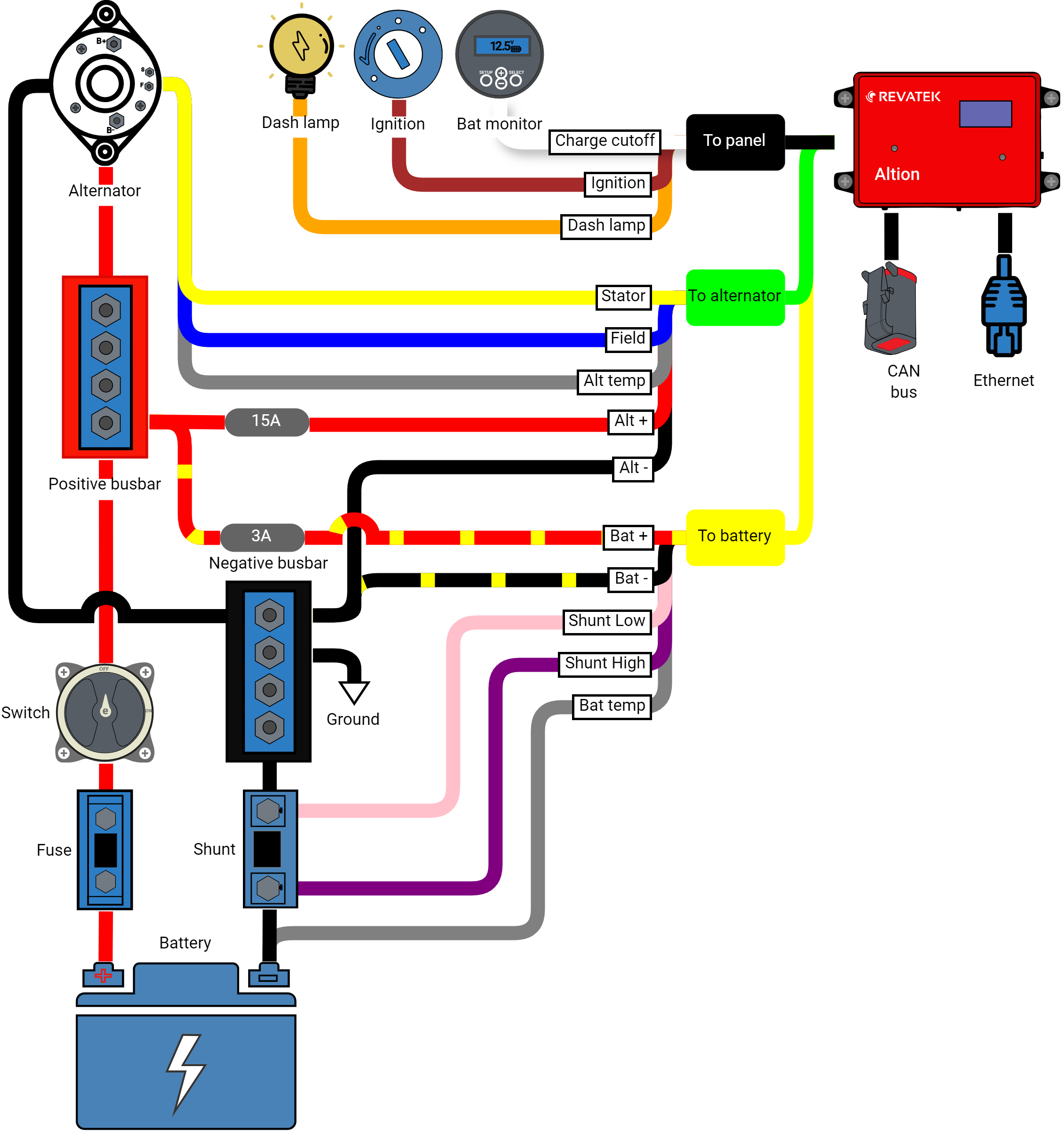
This section will walk you through installing the wiring harness for your Altion voltage regulator. We've included a comprehensive wiring diagram, a detailed wire descriptions table, and helpful tips for a smooth and successful installation.
Understanding your wiring harness
Altion voltage regulators come with wiring harnesses designed for compatibility with your specific model. There are two main harness configurations:
- Single alternator harness (standard): Suitable for systems with a single alternator. It features three sections, each with color-coded wires for easy identification.
- Dual alternator harness (Altion max only): Exclusive to the Altion Max model, this extended harness is designed for systems with dual alternators. It includes two additional sections sleeved in blue and white to accommodate the second alternator and an additional battery. The wire colors within these sections match the standard harness designations, but they connect to the additional alternator and battery bank respectively.
Refer to the wiring diagram below for a visual representation of the single alternator harness (standard). The Altion Max uses the same wire colors and connection instructions. See the following table for a detailed breakdown of wire names, colors, and functions, which applies to both the standard and Altion Max configurations.
Wiring diagram
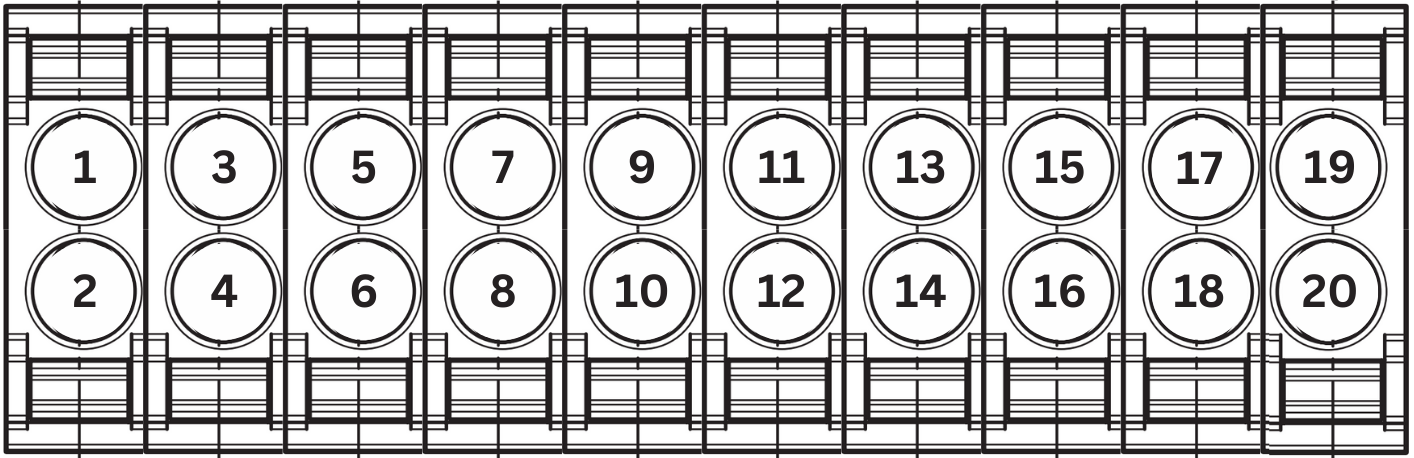
Connector pin numbering
Use these pin numbers and the wiring table below if you need to replace wires. The stock harness uses 18 AWG wire for connections except for Alt +, Alt -, and Field, which use 14 AWG. For extended runs use thicker wire. In most installations, stock wiring is sufficient.
Connector A
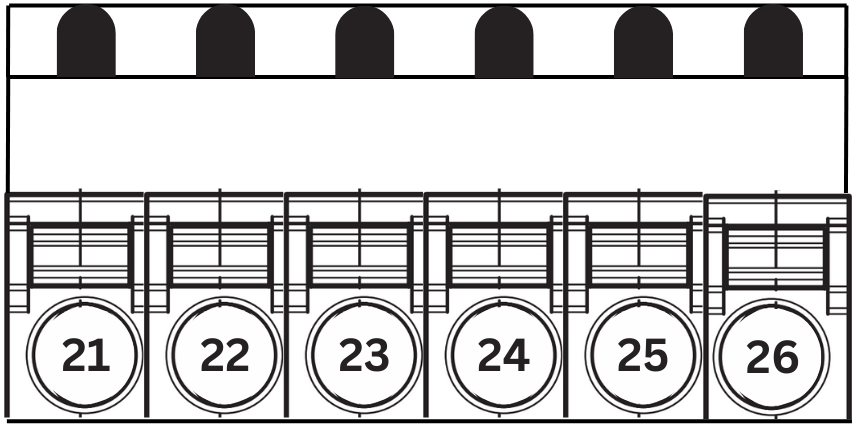
Connector B
Wiring table
Panel wiring harness (black sheathing)
Connector Pin numbers are listed with alternator 1 and battery 1 first, followed by alternator 2 and battery 2, if applicable.
| Wire Name | Color | Description | Connector Pin |
| Ignition | Brown | Provides switched power to the Altion regulator. Connect to ignition switch, oil pressure switch, or a similar circuit active only when the engine runs. For always-on battery monitoring, connect to a positive bus bar (required, 8-60V). | 1, 2 |
| Dash lamp | Orange | Provides a ground path to activate a warning light or audible alarm in the event of a fault condition (optional, 8-60V, 2A max) | 19 |
| Charge cutoff | White | Configurable function to stop charging when the signal line crosses 2V (trigger level adjustable, optional, 0-60V). | 7, 13 |
Alternator wiring harness (green sheathing, blue for Alternator 2 in Altion Max)
| Wire Name | Color | Description | Connector Pin |
|---|---|---|---|
| Alternator Temp | Gray | Connects to alternator temperature sensor. Improves efficiency and protects alternator by regulating field output based on temperature. Mount on rear case or ground terminal. | 8, 5 |
| Alt - | Black | Provides ground to the regulator. Connect to negative bus bar or alternator's negative ground terminal. Ensure clean connection to bare metal. | 23, 26 |
| Alt + | Red | Supplies power for the alternator field. Connect to the positive bus bar or alternator's positive output post. Fuse at 15 amps. (8-60V) | 21, 24 |
|
Field |
Blue | Carries field current between the regulator and alternator. Polarity varies based on alternator type. Fuse if recommended by alternator manufacturer (common for N-type, 16A max). | 22, 25 |
| Stator | Yellow | Provides signal for alternator and engine RPM. Connect to alternator's stator (AC) output or splice into the tachometer output. | 4, 3 |
Battery wiring harness (yellow sheathing, white for Alternator 2 in Altion Max)
| Wire Name | Color | Description | Connector Pin |
|---|---|---|---|
| Bat temp | Gray | Connects to battery temperature sensor. Adjusts charging voltage based on battery temperature, critical for lithium batteries in cold climates. | 10, 16 |
| Bat - | Orange | Improves charging accuracy by monitoring voltage at the battery's negative bus bar or terminal. Connect to the same negative terminal post as the ground cable in multi-battery setups. | 11, 17 |
| Bat + | Black w/ Yellow Stripe | Improves charging accuracy by monitoring voltage at the battery's positive bus bar or terminal. Fuse at 3 amps. Connect to the same negative terminal post as the ground cable in multi-battery setups (8-60V). | 14, 20 |
| Shunt high | Red w/ Yellow Stripe | Connects to the high side of a battery shunt, toward the battery. Measures current flow for charging optimization and battery health. Refer to the diagram. Minimize extension length, use twisted wire if needed. Can be added to existing wiring, so multiple devices can read from a single shunt. |
12, 18 |
| Shunt low | Pink | Connects to the low side of a battery shunt, toward the negative bus bar. Refer to the diagram. Minimize extension length, use twisted wire if needed. | 9, 15 |
Installation instructions
Before installing or working on the Altion regulator, disconnect all power sources and remove the negative battery terminal to prevent electrical shock and equipment damage.
Step 1: Connect wires to the alternator
- Locate the corresponding wires on your alternator following the manufacturer's instructions.
- Strip a small section of insulation (typically 1/4 inch) from the ends of the designated alternator wires (refer to the wiring table and diagram).
- Use compatible crimp terminals (refer to your alternator's manual for terminal type) and secure them to the stripped wire ends using your crimping tool.
- Carefully connect the matching colored wires from the alternator section of the wiring harness to the corresponding terminals on your alternator. For the Altion Max, refer to the wiring table and diagram for connections to the second alternator (blue sleeved section).
Step 2: Connect wires to the battery bank
- Locate the positive and negative battery terminals on your battery bank (and the additional battery bank for Altion Max).
- Strip a small section of insulation from the ends of the designated battery wires (refer to the wiring table and diagram).
- Use compatible crimp terminals and secure them to the stripped wire ends.
- Connect the battery wires to your battery bank(s) according to the wiring table and diagram, paying close attention to connections for the additional battery in the Altion Max (white sleeved section).
Step 3: Connect wires to the panel
- Locate the ignition switch, warning lamp connection point, and any designated points for custom functions on your system's control panel.
- Strip a small section of insulation from the ends of the designated panel wires (refer to the wiring table and diagram).
- Use compatible crimp terminals and secure them to the stripped wire ends.
- Connect the panel wires to your system's control panel according to the wiring table.
Step 4 (optional): Connect to CAN Bus
- Connector: The Altion uses a DTM connector for its CAN bus connection, allowing direct compatibility with RV-C networks. A DTM to NMEA 2000 (M12 connector) adapter is included for connecting to NMEA 2000 networks.
- Termination: Proper termination of the CAN bus is critical for reliable communication. If the Altion regulator is the last device on the CAN bus backbone, set the CAN bus terminator switch to the ON position (switched to the right). This adds a 120-ohm resistor between the CAN High and CAN Low lines. The Altion is installed on a drop line (not the last device on the backbone), in which case the switch should remain off (to the left).
Terminating the CAN bus at more than two points can degrade its performance. You can use a multimeter to test for proper termination by measuring the resistance between CAN High and CAN Low. It should read approximately 60 ohms if the network is properly terminated at both ends.
Step 5: Secure and organize the wiring harness
-
Connect the two alternator harness connectors and align them with the corresponding slots on the left side of the regulator. The connectors are keyed, which means they are designed to fit only in a specific way. Carefully insert the connectors into the slots, making sure that they are fully seated.
-
Double-check all connections: Before applying any power, take a final moment to visually inspect all wire connections for secure crimps and proper placement on the designated terminals.
-
Secure the Wiring Harness: Use zip ties or other suitable fasteners to secure the wiring harness at regular intervals along its length.
-
Route the Wiring Harness: Carefully route the excess wiring harness to avoid any pinch points, hot engine components, or areas with high abrasion potential.
-
Maintain Slack: Allow for some slack in the wiring, particularly near the alternator, battery bank, and control panel connections.
If you need to extend the CAN bus, voltage or temperature sensor cables, use twisted pair wires. For electrically noisy environments, consider using shielded instrument cable for added protection.
With these detailed steps, the comprehensive wiring table, the included wiring diagram, and the added CAN bus instructions, you can ensure a successful and trouble-free installation of your Altion voltage regulator wiring harness.